Detection
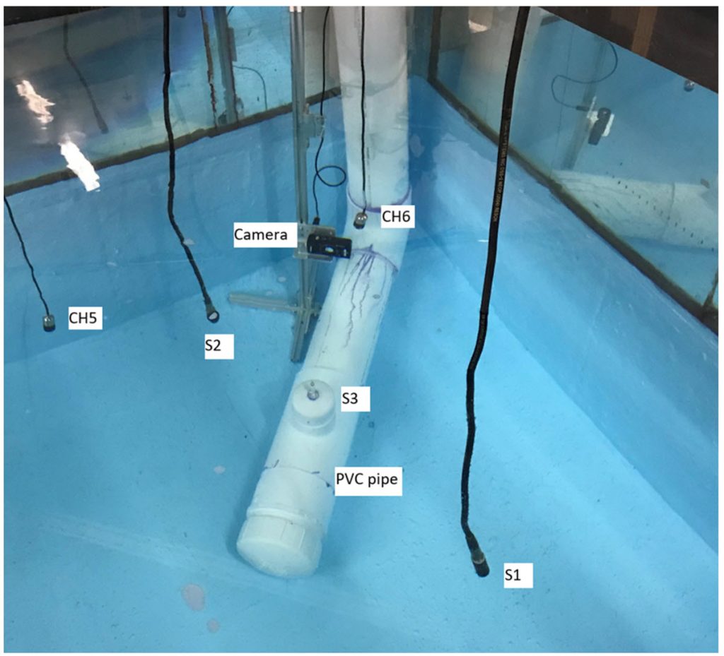 The water tank experimental setup
 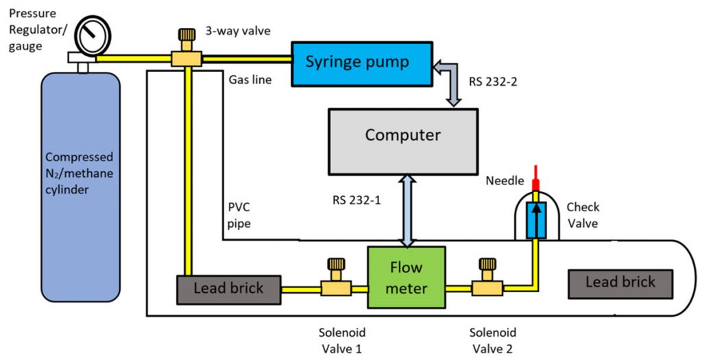 The schematic diagram of the bubble generation system.
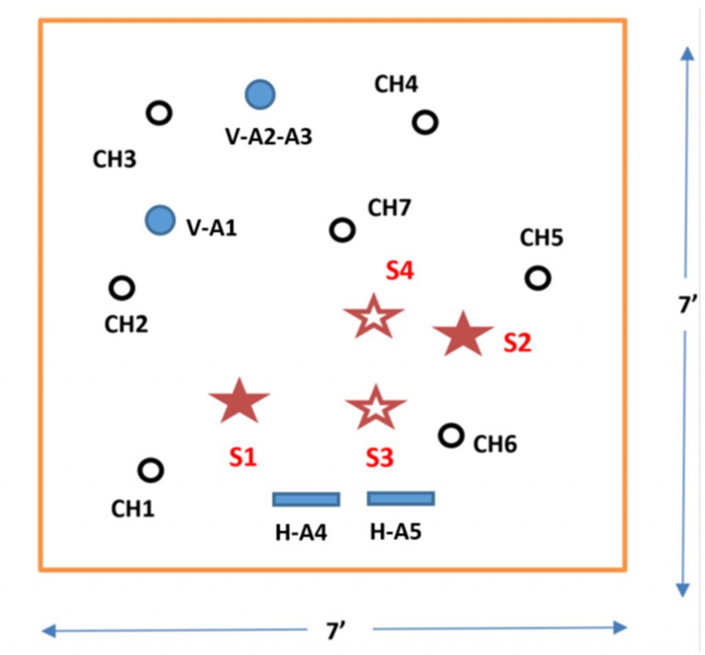 The top view of acoustic sources (S1- S4), hydrophones (CH1-CH7), and vertical and horizontal hydrophone arrays (V-A1, V-A2, V-A3, H-A4, and H-A5)
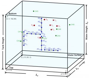
3D view of acoustic sources, hydrophones, and hydrophone arrays from the bottom to the top
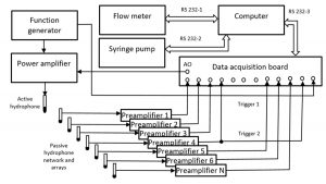 The schematic program for instrument control and data acquisition
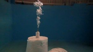 Photo for constant flow bubbles
 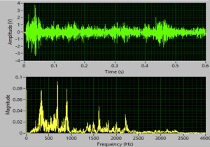 The signal for constant flow bubbles in time and frequency domains
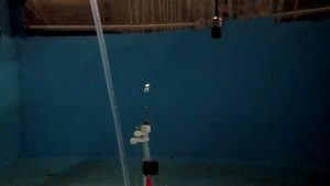 Photo for a few bubbles
 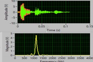 The signal for a few bubbles in time and frequency domains
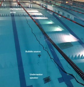 Swimming pool test